⇒TRANSFORMATION OF MOTION⇐
ROTARY-LINEAR TRANSFORMATION
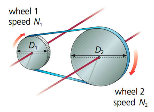
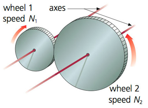
WHEEL
Wheels reduce contact with the ground and decrease friction. If there isn't enough friction, they can slide out of control. We need less force to move vehicles with larger wheels and they move more quickly.

RACK AND PINION
This mechanism has two parts: the rack is a bar with many theeth and the pinion is a gear with theeth that interlock with the rack. It transforms rotary motion into linear motion.
NUT AND BOLT
This mechanism transforms rotary motion into linear motion. It has two parts: a bolt with a spiral groove and a nut that turns around it.

WINCH AND CRANK
It is a cylinder that rotates around a horizontal axis. We turn the crank to rotate the winch. The crank increases the force and the winch transforms rotary motion into linear motion. This mechanism has the Law of the Lever.


It is a cylinder that rotates around a horizontal axis. We turn the crank to rotate the winch. The crank increases the force and the winch transforms rotary motion into linear motion. This mechanism has the Law of the Lever.
RECIPROCATING ROTARY-LINEAR TRANSFORMATION
CRANKSHAFT
We can conect multiple rods to one shaft. The rods are connected to cranks, and the cranks are connected to the crankshaft. It can synchronise the movements of various parts.
CAM
A cam is a irregulary device that rotates on a shaft. When the cam rotates, it pushes a special bar called follower. This follower can move other parts or it can turn a switch on and off.
When we put multiple cams on a shaft, it's called a camshaft. We can use it to synchronise the movements of various parts.